 | ||||
The page will generally describe the inner workings of the DragonRail. Broken down in sub sections, each is described in basic detail on it's function. Below is a rundown of the sections...
Display Effects Explained: Images of key components of the LED display components. Audio and the Front Aperture: Audio IC, amplifier and the speaker assembly. Housing Assembly: Various images of the outer skin of the railgun and the display diffuser parts. Power Supply and Vibration Motor: The tactile feedback mechanism and the power supply components. Old Assembly Pictures: Three early production images. Pretty low quality pictures but they are what they are.
Sorry but no schematics are shown, gotta keep some of that magic alive. =)
Below again is the embedded YouTube video. | ||
| ||
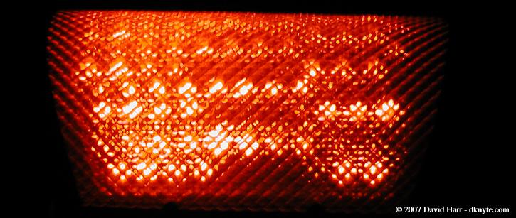 | ||
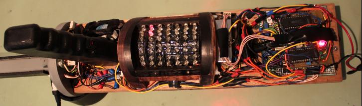
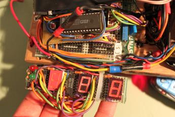
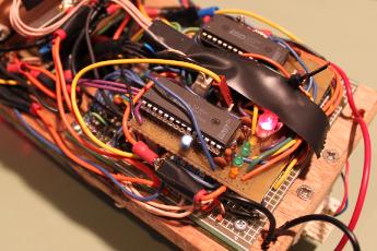
The upper visual effects array consists of 13 rows containing 146 red high-brightness LED's total. They are staggered such that the outer most rows have 10 LED's per row, then 3 rows of 11 LED's each side then 5 rows of 12 LED's in the top-most center. These rows are made active by both a 7x counter and a 6x counter. These counter control the switching of transistors that activate each row one at a time per relative said counter. They also activate in the opposite direction of each other so the LED's appear to cross each other. The following example illustrates how the rows are interleved. The bold numbers are controlled by the 7x counter and the italic ones by the 6x counter.
10 11 11 11 12 12 12 12 12 11 11 11 10 Bold: 7x Italic: 6x
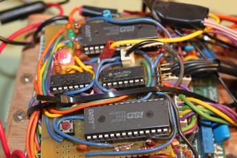
The data for each of the counters is supplied by a 556 timer. A 556 is an IC that contains two 555 timers in one discrete chip. One of the timers is at a set speed and the other is controlled by a potentiometer that the user can control. The timers' output might be considered "dirty." This dirty signal, which is on purpose, gives the appearance of randomness to the on/off states of the LED's. The output of each timer is then fed into a series of shift registers to move the LED signals linerally towards the user. A decade counter controls the speed of the shift registers which is user controlable. | ||
| |||||||||||||
| |||||||||||
| |||||||||||
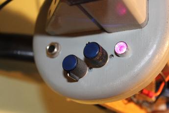
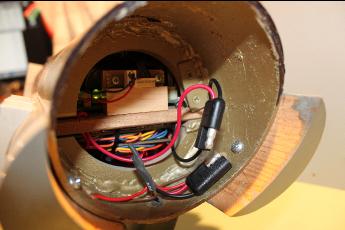
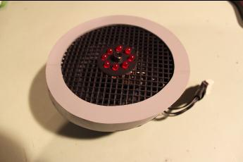
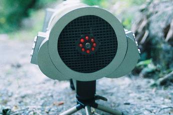
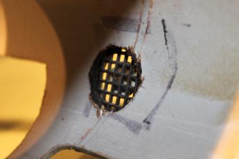
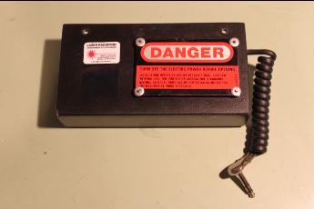
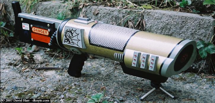
The front of the railgun has a cluster of 8 LED's with a laser pointer in the center. When the guns' trigger is pulled, the 8 LED's go blank and the laser pointer activates. The 8 LED's and the laser are suspended in the center of the speaker grill which protects the speaker.
The speaker plays the audio from two recordable IC's. While the railgun is on, a custom looped hum is played to simulate the power of the weapon model. When the trigger is pulled, not only does the aformensioned forward LED's and laser do their thing but a shooting sound is played.
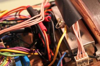
Also, when the trigger is pressed, a 12V motor with a counterweight spins up and causes the entire railgun to vibrate slightly.
There are 9 LED's on the front trim panels on both sides. They just stay on. | ||
| |||||||||||
| |||||||||||
| |||||||||||
| |||||||||||
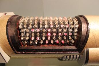
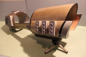
The railgun housing was made with a thick cardboard tube. Sonotube varient. After building the inner housing, we measured where the displays would sit, then cut out the appropriate angles. It wasn't until after final paint that the outer tube winding was noticable. Oh well.
The paint was one of those textured rattle-can variety. I can't recall the brand, style or whatever. After doing some test sprays on some sample pieces, the best result I wanted was a semi-heavy last coat and set the housing vertical. This gave a cool texture dripped effect towards the rear of the gun.
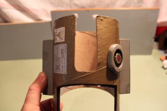
The housing is keyed to the inner frame as shown in the first picture below.
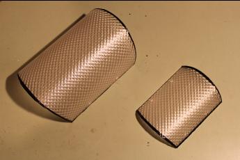
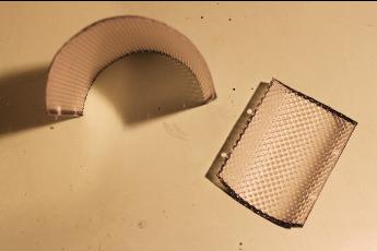
The last 2 picts in this section show the plastic covers for both displays. They were made from fluorescent light fixture diffusers. The trickiest parts was getting them to bend without breaking. We made a jig with the same inner diameter as the tube and used a heat gun and slowly shaped them around it. Drilling the holes was a no-go with a standard drill. Even though the plastic is durable, it has a certain brittlness to it. Drilling could cause it to split. So we used a dremmel tool to make the holes. | ||||
| |||||||||||
| |||||||||||

| |||||||||||
| |||||||||||
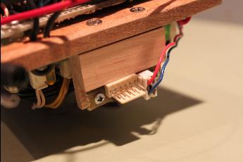
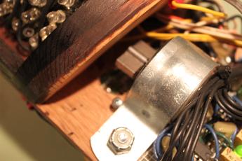
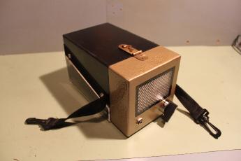
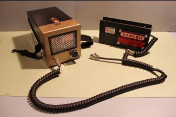
One 12V lead acid battery is housed on the stock of the railgun. Another is supplied from a seperate matching power cell case that can be carried ofer the shoulder. Both are connected by a power cord to a port on the rear control panel.
An external power cube/wall-wort can also be used if portability is not needed.
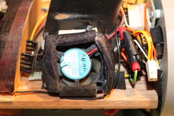
The first image is the tactile vibration feedback motor. It runs off of 12 volts and has a good size counterweight. | ||
| |||||||||||
| |||||||||||
| |||||||||||
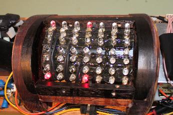
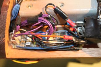
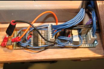
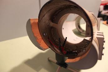
These are some older images during construction. You can make out some of the early construction progress. The picts were taken with a crap-tastic web-cam.
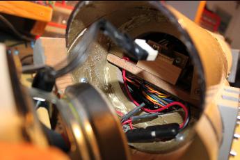
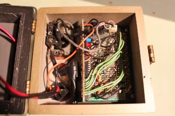
The first image is the inside of the gun. This is the main inner frame that also supports the electronics.
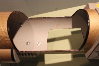
The second is the raw housing installed over the frame. You can see that the slot is cut to allow the LED's to shine on thru.
The last is the aperture with the grill and front LED module installed for a test fit. | ||
| |||||||||||||||||
 | ||