 |  | |||
 | ||||
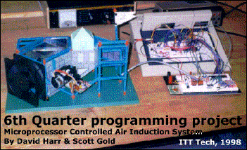
Temperature Controlled Pulsed Air Induction System 2000 This was the final project that my friend and classmate Scott Gold and I built together to complete the requirements for our 6th quarter at ITT Tech. The class was Microprocessor Programming. We learned the fundamentals of hexadecimal programming using a Motorola MC6811 trainer. Both the Lab and theory portions of this quarter were taught by Mr. Mortenson. The theory portion of the quarter was more specific towards programming the MC6811 but the premises taught apply to all forms of hexadecimal programming ranging across many microprocessors available on the market today. The final project was a Temperature Controlled Pulsed Air Induction System. When the circuit measured the ambient air using an LM35 thermal controlled transistor, the microprocessor would control a stepper motor which was attached to a vane that regulated the amount of airflow through an air duct. This temp sensor, ideally, would be connected to a component such as a motor or within the coolant stream of a nuclear reactor (wishful thinking.) When the temperature reached a preset value, the motor would turn constantly. This constant turning of the air vanes within the air duct would cause a cycling stream of air to cool the component. This was so the component would not be cooled too quickly and to allow for temperature stabilization. This stabilization should cause the component to operate at a steady level without worry of overheating. This running temperature could be preset to the optimum temperature that component runs at for it's greatest efficiency. The original design called for the temp sensor feeding a standard 741 Operational Amplifier which outputted an analog voltage to an Analog to Digital Converter (ADC 0809) with 256 individual binary equivalents of the inputted analog signal. This could give us very good accuracy but we opted for a smaller range to simplify the project. A digital equivalent to the analog voltage was outputted to a Parallel Interface Adapter (PIA 6821) which was used to interface the trainer's built-in MC6811 processor. The processor would then be able to see the value that the temp. sensor. If it went to or beyond a certain value, the processor would call upon a subroutine to activate the stepper motor. This was done by sending four 4 bit binary lines to the PIA, which in turn activated each step of the stepper motor. The stepper motor is different than a conventional motor. A conventional motor just turns in a direction depending on the voltage and that voltage's polarity on 2 wires. A stepper motor has 5 wires. 1 common and the other four are the binary inputs. Depending on the position of the motor, an alternating binary value is sent on these four wires. I'll illustrate them as follows....
etc... It could be easier explained if you divide the 4 bits into 2 pairs of 2. For each step of the motor to occur, only 1 pair of the two should change states. Also, when one pair changes states, the other pair of bits need to change. If you notice in the illustration below, at any given step, only one pair is changing it's state at a time and then alternates to the other pair when that step is executed. this is the premis behind stepper motors. | ||
| |||||||||||||||||||||||||||||||||||||||||||||||
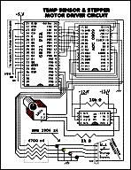
The alteration in this manner would cause the motor to turn in one direction, say clockwise. If you wanted the motor to turn counterclockwise, you would just reverse the order of those 4 four bits. In other words, if you went CW with 0101, 0110, 1010, 1001 then you would go 1001,1010,0110 and 0101 to go CCW. The speed of the motor is dictated by how quickly each step is executed. In the circuit, the PIA drives 3904 transistors so that the current drain the stepper motor is away from the PIA. Current limiting resistors are also used on the bases of these transistors. Below is a schematic of the temp. sensor circuit, the ADC, the PIA and the stepper motor. Main Circuit
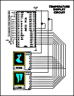
The original design called for an additional PIA to drive 2 7-segment displays to give the user a visual readout of the temperature being read by the MC6811. Unfortunately, we ran out of time to debug the code required for the implementation of this portion of the project. I know we could have gotten it to work if we had another day to work on it. Maybe next time. =) Display Circuit
The idea behind the display was to have an additional subroutine that utilized a lookup table to that the temp. value read by the MC6811 would be outputted to another PIA. This additional PIA was multiplexed with the first PIA. The display PIA would then multiplex the anode of the two displays. On each multiplex of the displays, the Least Significant Digit and the Most Significant Digit would display the value on the PIA's output data bus. The program would alternate the value of the bus in synch with the respective anode so the actual temp. would be displayed. Above was the schematic we drew up. Unfortunately, the program code that we wrote for this project is unavailable for me to show here at the time of this writing. When it becomes available, I'll put it here. With the help of the program description below the software could be written again to be processor specific if you wanted to try it out. Processor Steps
DPIA Sub
Conclusion It looks suprizingly simplistic, but it came out to more than 75 lines of code. The lookup tables and the stepper motor subroutine took a lot of memory. The stepper motor code needed to utilize an incrementing accumulator routine to read and store the value of the correct step that the motor needed from its own lookup table. There much juggling of numbers to get it to work correctly. The best bet is to use a processor that has either a wide accumulator storage allocation or one with multiple accumulators. The MC6811 uses 2 accumulators (ACCA and ACCB) and this was just enough. Who knows, with code optimized for a specific processor one might be able to get away with a cheaper version processor. =) All in all, this was a fun project to build. Working with Scott Gold helped me learn much throughout the quarter. I would work with him again on a project any day. Thanks Scott! | ||