Circuit Design Two seperate laser emmiting armatures were constructed. Each with it's own pair of frequency generators that controlled each axis. Each armature shared a different type of salvo design. The smaller of the two used an electromagnetic style salvo. They have their own +12, ground and input leads. The main laser uses a permanent magnet type salvo that works just like a speaker coil, only the magnet is on it's side and the coil pivots on an axis. Then a signal is applied to either of these salvos, a 'wobble' occures with the mirrors and the projected beam. Enough of this blurb, read on... =) The Primary Laser First off, I'm only going to give half the story as it pertains to one of the two axisies. If you get this half to work for one waveshape, just build a copy for the other axis. It's that simple... anyway, here's the flow-chart... 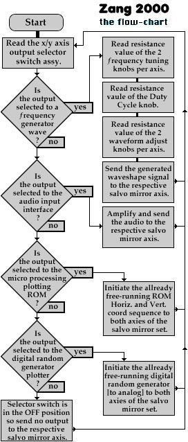
An XR-8038 precision frequency generator is used because of it's simple hookup and output lines. These IC's are a straight up and hassle-free. We wanted as much control of the waveshapes as possible. We can adjust the frequency, duty cycle, and wave shape symetry to SIN, Triangle and Square wave outputs. Some adjustments are more prevelant with various shapes and others may have no effect (this is normal). Here's the schematic... 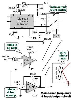
To calculate the freq. range desited do not use the standard 1/(2piRC)! Use the formula 0.15/(RC) instead. Potentiometers come in standard ranges, so pick your upper frequency roll-off point and calculate C. The R of the calculation is across pins 4 and 5. To obtain our duty cycle, a 5k Pot was placed across pins 4 and 5 so that the center tap connects to I think a 1M pot. This acts as a voltage divider causing a voltage unballance between 4 and 5. The larger pot that controls frequency is connected as a voltage divider. One pin and the center tap going to Vcc +12v and the last pin going the the duty cycle center tap. If you need a fine tuner, add a smaller pot of about 50K ohms. If you do, don't forget to recalculate your value of C. - • Pin 10 is C to ground
- • Pin 6 is to +Vcc 12v
- • Pins 7 and 8 are jumped. May be able to produce a modulated output frequency but the spec. sheet is vague about it's usage.
To get wave shape symetry, two 100k ohm pots are used. They are center tapped and voltage divided between +Vcc 12v and Ground. These center taps go to the input pins 1 and 12 respectivly. The XR-8038 can produce 3 individual outputs at the same time. - • Pin 2 is output SIN
- • Pin 3 is output Triangle
- • Pin 9 is output Square. [Note: You must install a current limiting resistor from pin 9 to +Vcc 12v. @ about 2k ohms]
These outputs go to a selector switch where the common lead goes to a 741 op-amp to drive the respective salvo axis. Hookup for this amp is simple and it contains a gain of 10 which is calculated by the ratio of Rf/Ri. You may need to install a coupling cap in series with your pre-amped signal to Ri. Anyway, here's the pinout for this 8 lead op-amp. - • Pin 7 +Vcc 12v
- • Pin 4 -Vcc -12v
- • Pin 2 inverting input resistor [Ri] (about 5k ohm)
- • Pin 6 to Pin 2 feedback resistor [Rf] (about 50k ohm)
- • Pin 6 amplified output
- • Pin 3 non-inverting resistor to ground
- • Pin 1 no connect
- • Pin 5 no connect
With everything hooked up, you can check the output with an o'scope. You should be able to do the following... - 1. Adjust frequency from approx <25Hz to about 500+ Hz with 2 pots (course and fine).
- 2. Adjust duty cycle with 1 pot.
- 3. Adjust wave shape symetry with 2 pots.
- 4. Amplification from the selected wave and the 741 output pin 6.
- 5. Select the output wave signal with a multi selector switch.
You can have an audio signal applied to the salvo amps. I reccommend using an RCA connection with a fixed peak-top-peak limit. This may require a preamp whose output goes to the axis selector switch. This will ease the selection of what axis signal is applied to the respective salvo. You could use a preamped signal like for headphones from a cd player. You should pay attention to the high end volume output level. You nay need to rethink your preamp stage for circuit protection, the salvos can only handle so much voltage. Refurbished salvo's are cheaper and they rarely come with a spec. sheet. Start with low gain and slowly work up. If everything here works, build an identical circuit for the other axial input to the salvo. With this, you can select a different input signal/shape for each axis. Adjusting the pots gives some interesting results. The main salvo is driven by a 15 mW Helium-Neon (HeNe) class IIIB laser. The Secondary laser The premis is the same for this armature. Only we didn't need the extreem control like with the main laser. We went to only adjust the frequency of SIN and select an allternate sound input. This also having the option of turning off an axis. Again this is described for a single axis. This circuit uses the XR-2206 Monolithic Function Generator. The rundown will be quick because you should derrive the essentials from the XR-8038 description. Here, goes. - • Pin 1 Ground
- • Pin 2 SIN output
- • Pin 3 no connect
- • Pin 4 +Vcc 12v
- • Pin 5 Timing Cap [C] to Pin 6
- • Pin 6 Other end of Timing Cap from Pin 5
- • Pin 7 Timing Resistor [R]
- • Pin 8 no connect
- • Pin 9 no connect
- • Pin 10 no connect
- • Pin 11 no connect
- • Pin 12 Ground
- • Pin 13 200 Ohm to Pin 14
- • Pin 14 Other end of 200 Ohm from Pin 13
- • Pin 15 no connect
- • Pin 16 no connect
Here's the schematic... 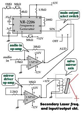
And here's the flow-chart... 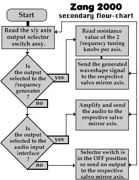
To calculate the freq. range desited do not use the standard 1/(2piRC)! Use the formula 1/(RC) instead. The value of pi is compensated for w/in the IC and you can superimpose again to calculate C. If you use a 500k Ohm pot for R, your RC frequency should be relativly the same as the XR-8038. We used a .15microF for all 4 function generators. The spec. sheet had examples of wiring the IC, but we found we could remove some of the components and the XR-2206 worked just as well for what was desired. The controls are as follows: - • 2 frequency adjusters with Coarse and Fine adjustment
- • 1 three position ON/OFF/ON 'wave/off/audio' axial input switch dealie thing-a-ma-bob
Again a 741 op-amp was used to boost the signal up for the mirror set. This salvo is driven by a generic laser pointer. The Micro Processor by Jesse Kolstad In order to get specific characters to display with the LASER, we need processor power. The processor that I used is a Motorola M68HC(7)05C8A. This is an 8bit, 8K PROM with 300 Bytes of RAM. The processors drive two different 8bit DACs for the X and Y coordinates. I used a TLO72BCP as an amplifier/offset null for the two DACs. 
[Note from pm: The schematic is crude, but did exceptionally well in beta testing.] To display a character on the wall I must do a full x-y plot in a manner that can be traced linearly by an x-y mirror set with speed and inertia limitations. All this must be taken into consideration when programming. Since the mirrors are one hundred times slower than my processor, I must build in a settable delay that can be adjusted in real-time. 
[Click here to view a copy of the code Jesse wrote for this processor.] [note from pm: An additional circuit was constructed by Melody to accompany Jesse's processor. She built am 8-bit analog to digital converter which plugged into PC0 to PC7. With the use of a potentiometer, the processor speed could be adjusted on the fly. No schematics are available at this time.] The Random Quadrature Generator by Melody Sprinkel: The Psuedo Random Sequencer is one of the many combinations of Shift Register Feedback use. It can be of maximal length or one less then 2 to the nth -1. In our application, it is 2to the 4th -1 for 15. This is also known as a binary counter. The numbers appear in apparently random order or they repeat every time the sequence clocks through 15 where the randomness is constant over one total cycle. If Bits 3 &4 are both 0, or both 1, then a 1 is sent to the input of the first stage. If either, ( not both ) is a 0 then a 0 goes to the input of the first stage. This makes the numbers appear to be random. To do this, I had to research to find a suitable circuit which I found at Supertroniks in the Digital cookbook. Of course I had to integrate their idea to our needs by changing and adding my own ideas. I then drew a schematic made from a combination of a D Flip-Flop counter circuit run through an exclusive-or into an inverter and through a DAC. Then I needed a 555 timer to clock the FF's therefore found a need to calculate the components of the timer. The calculations are as pollows... The 555 timer frequency can be varied by changing timing components RA, RB, and C. - Freqmin/max = 1.44/(RA+2RB)C
- Frequency min = 1.44/(0+2(1K))(22uF) = 32.72Hz
- Frequency Max = 1.44/(40k+2(1k))(22uF)=1.55Hz
- Thus frequency can be varied from 32.72Hz to 1.55Hz.
- The duty cycle =[(RA+RB)/(RA+2RB)]x100%
- Min Duty Cycle = [(0+1k)/(0+2(1k))]x100%=50%
- Max Duty Cycle =[(40k+1k)/(40k+2(1k))]x100%=97.61
The repeat time is 1/15th of the clock frequency and can be varied from 1/15 of 32.72Hz=2.1813 seconds to 1/15th of 1.55hz=103ms The schematic below is the final design. 
After building the timer, I proceeded to wire the Flip-flops and then the DAC. The DAC IC proved to be too complex for our needs, so upon researching, replaced the chip with a simple discrete DAC made with a summing amplifier. Once that was complete, more testing was in order. Which found the circuit working well. The schematics were then revised, and the circuit went to David for further testing. It worked very well. We only needed to add one thing, a variable pot to the inverting input of the op-amp for a zero reference point. This worked also and centered the laser in the middle of the x and y coordinates. [note from pm: way to go melody! Great work!] The Power Supply by Jamie Garza: For out project we need a steady +12V (DC), -12V (DC), and a +5V (DC) output power supply. We built a power supply to complement the voltage requirements needed for the all the circuits in this project. By doing this we are not limited to an outside source for power. The only thing that we will need is an outlet. From the wall outlet, the cord is connected to the transformer. There is a 1A protect fuse connected to line in. 0V line out of the transformer is connected to ground. From the transformers 14.5V (AC) line out is connected to the input to the 9030 IC (Bridge Rectifier), which rectifies the AC voltage to DC voltage. The voltage coming out of the rectifier is approximately 18.25V (DC). From the negative and positive outputs of the 9030IC are connected to two 10,000microF capacitors. From the positive end of one of the 10,000microF capacitors connected to the input of the 7812CT IC (+12V Regulator). The 7812CT IC changes the +18.25V(DC) input to a +12V (DC) output. The output is connected to the +12V selection of the terminal block and to the positive end of one of the 10microF capacitor. The negative end of the 10(F capacitor is connected to ground. From the output of the 7812CT IC also goes into the input of the 7805CT IC (+5V Regulator). The 7812CT IC changes the +12V (DC) input to a +5V (DC) output. The output of the 7805CT IC is connected to the +5V selection of the terminal block and also connected to the positive end of the third 10(F capacitor. From the negative end of the 10(F capacitor is connected to ground. The actual output measurement from the 7812CT IC is +12.07V (DC) and from the 7805CT IC is +4.97V (DC). From the negative end of the other 10,000microF capacitors is connected to the input of the 7912CT IC (-12V Regulator). The 7912CT IC changes the -18.25V (DC) input to a -12V (DC) output. From the output the 7912CT IC is connected to the -12V selection of the terminal block and is also connected to the negative end of a 10(F capacitor. The positive end of the capacitor is connected to ground. Each IC has it's own ground connection which is connected to ground. The actual measurement from the IC is -12.08V (DC). 
All of these components are connected onto a simple breadboard. The components and placed on one side of the breadboard and connected on the other side of the breadboard by using wires and soldering the connections. |