 | ||
The xFire is an invasive controller mod that gives rapid fire functionality to the A button. With it the button can fire between 1 and 20 times a second.
To put it simply, a bypass was installed for the "A" button and a timer circuit board controlls a relay that simulates the button presses. A 4-pin connector taps into the circuit traces to allow the "A" button to activate the circuit. Two pins are for the "A" button electrical switch portion and the other 2 are routed to the part of the circuit that senses the switch press.
Figure 1 below is all the parts of the mod.
> xFire driver board: The circuit board that includes a 555 timer, relay, timer speed dials and function switches. > xFire connector: This connects the driver board to the modded controller. > Power supply: This powers the driver board. > Xbox controller: A standard wired controller. > Bypass plug: This bypass connector can be installed instead of the driver board to allow normal operation of the controller.
Additional illustrations and pictures are below. | ||
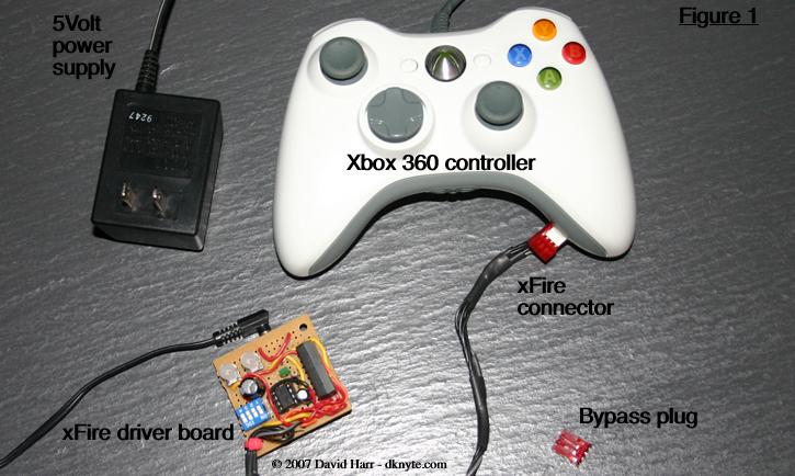 | ||
Figure 2 is the xFire driver board.
> 555 timer IC: This is the heartbeat IC of the xfire. > Firing relay: This is the relay that is controlled by the timer. The timer activates this highspeed relay and it's internal switch controls the "A" button. > Speed dials: These variable resistors control the speed of the 555 Timer. > Speed indicator LED: This shows the user just how fast the switching is during operation. > Function switches: SW1 allows a diffent multiplier to allow the timer to pulse at an extreamy low speed if necessary. SW2 and 3 allows a temporary bypass so the driver board operates as if it wasn't there. > Power Plug: This powers the whole board with 5Volts DC. | ||
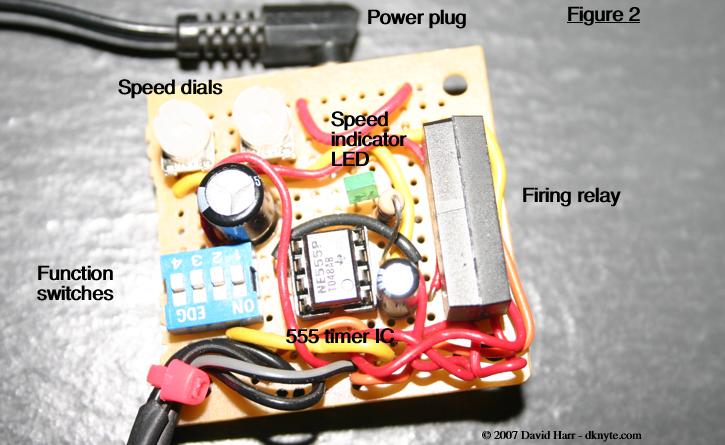 | ||
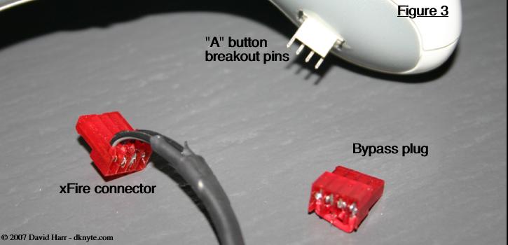
Figure 3 is the connector interface for the xFire to the controller. > Button breakout pins: These are the 4 pins that bylass the button switch. > xFire connector: This is the connector to the xFire controller board. > Bypass plug: This is the bypass plug so the controller works as normal if installed instead of the xFire. | ||
 | ||
I didn't take any pictures of the innards during the hack (gak). What I will tell you is it's necessary to desolder the pins of the right trigger potentiometer to gain access to the controller circuit board. The traces are super small so a very fine guage wire was used.
Additionally, take care routing the wiring away from the vibration motor. Or just remove the motor (there's a small connector on the circuit board, pull gently). | ||