 | ||
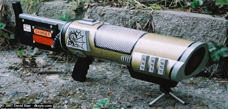 | ||
This web page is to illustrate the working of the DragonRail. This was a project that was inspired after the Railgun from the Quake series of games by ID software, this puppy is made of wood, plastic, a cardboard tube and a bunch of home-brew internal electronics. Following my design, the total build from concept to finalization took about 6 months.
The framework and housing were build by my design with the aide of my buddy Rob Good at Black Hills Cabinet and Fixure.
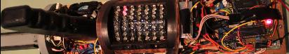
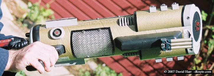
In the following, I will describe some general principles of the railguns' construction both inside and out.
Features of the DragonRail are as follows...
• User controllable visual effects • Rubber hand grips • Laser pointer arperature • Built-in display stand • Vibration feedback • Audio rail-hum and shooting sound effects • Stock mounted & external slung power cells
• Length, height and width: 32.5" x 8.5" x 7.5" (82.6cm x 21.6cm x 19.1cm) • Railgun weight w/ stock power cell: apprpx. 10 lbs. (4.5 kg) • External power supply: 3 lbs. (1.36 kg) | ||
Watch the YouTube video below for a look inside! < 14 minute runtime > | ||
 |  | |||
 | ||
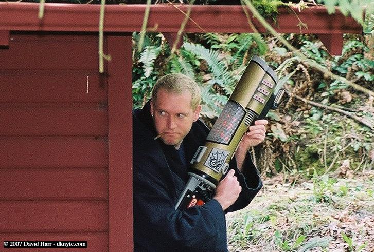
And finally some picts of me acting stoopid with the Dragonrail. | ||
 |  | |||
 | ||